2d to 3d drawing conversion jobs
| Process type | digital and print |
|---|---|
| Industrial sector(s) | Film and television, impress production |
| Main technologies or sub-processes | Computer software |
| Product(s) | Movies, telly shows, social media, printed images |
2D to 3D video conversion (likewise called 2D to stereo 3D conversion and stereo conversion) is the process of transforming 2nd ("flat") film to 3D form, which in almost all cases is stereo, then it is the process of creating imagery for each eye from ane 2D image.
Overview [edit]
2D-to-3D conversion adds the binocular disparity depth cue to digital images perceived by the brain, thus, if washed properly, profoundly improving the immersive effect while viewing stereo video in comparison to 2nd video. However, in order to be successful, the conversion should be washed with sufficient accuracy and correctness: the quality of the original 2D images should not deteriorate, and the introduced disparity cue should not contradict other cues used past the brain for depth perception. If washed properly and thoroughly, the conversion produces stereo video of similar quality to "native" stereo video which is shot in stereo and accurately adjusted and aligned in postal service-production.[1]
Two approaches to stereo conversion can be loosely defined: quality semiautomatic conversion for movie house and high quality 3DTV, and depression-quality automatic conversion for inexpensive 3DTV, VOD and similar applications.
Re-rendering of computer blithe films [edit]
Computer animated 2nd films made with 3D models tin can be re-rendered in stereoscopic 3D by adding a 2d virtual photographic camera if the original information is still available. This is technically not a conversion; therefore, such re-rendered films have the same quality as films originally produced in stereoscopic 3D. Examples of this technique include the re-release of Toy Story and Toy Story two. Revisiting the original calculator data for the two films took four months, as well as an boosted six months to add together the 3D.[2] However, not all CGI films are re-rendered for the 3D re-release because of the costs, time required, lack of skilled resource or missing computer data.
Importance and applicability [edit]
With the increase of films released in 3D, 2D to 3D conversion has get more common. The majority of not-CGI stereo 3D blockbusters are converted fully or at least partially from 2nd footage. Even Avatar contains several scenes shot in 2D and converted to stereo in post-production.[3] The reasons for shooting in 2D instead of stereo are financial, technical and sometimes creative:[1] [4]
- Stereo post-production workflow is much more circuitous and not as well-established every bit 2D workflow, requiring more work and rendering.
- Professional person stereoscopic rigs are much more expensive and bulky than customary monocular cameras. Some shots, particularly activity scenes, tin can be only shot with relatively pocket-sized 2nd cameras.
- Stereo cameras can introduce diverse mismatches in stereo image (such equally vertical parallax, tilt, color shift, reflections and glares in dissimilar positions) that should be fixed in post-product anyway because they ruin the 3D upshot. This correction sometimes may have complexity comparable to stereo conversion.
- Stereo cameras can beguile applied effects used during filming. For example, some scenes in the Lord of the Rings movie trilogy were filmed using forced perspective to allow two actors to announced to be unlike physical sizes. The same scene filmed in stereo would reveal that the actors were non the same distance from the camera.
- Past their very nature, stereo cameras have restrictions on how far the camera tin be from the filmed subject and even so provide adequate stereo separation. For example, the simplest way to film a scene attack the side of a building might be to use a camera rig from across the street on a neighboring building, using a zoom lens. However, while the zoom lens would provide acceptable epitome quality, the stereo separation would be virtually nix over such a altitude.
Fifty-fifty in the case of stereo shooting, conversion can oftentimes be necessary. Besides the mentioned hard-to-shoot scenes, at that place are situations when mismatches in stereo views are too big to adjust, and it is simpler to perform second to stereo conversion, treating 1 of the views as the original 2D source.
Full general problems [edit]
Without respect to detail algorithms, all conversion workflows should solve the following tasks:[4] [v]
- Allocation of "depth upkeep" – defining the range of permitted disparity or depth, what depth value corresponds to the screen position (so-called "convergence point" position), the permitted altitude ranges for out-of-the-screen effects and behind-the-screen background objects. If an object in stereo pair is in exactly the same spot for both eyes, then it will appear on the screen surface and it will be in cipher parallax. Objects in front of the screen are said to exist in negative parallax, and background imagery behind the screen is in positive parallax. There are the corresponding negative or positive offsets in object positions for left and correct eye images.
- Command of comfortable disparity depending on scene blazon and motion – too much parallax or conflicting depth cues may crusade middle-strain and nausea effects
- Filling of uncovered areas – left or right view images testify a scene from a different angle, and parts of objects or entire objects covered past the foreground in the original 2d image should become visible in a stereo pair. Sometimes the background surfaces are known or can be estimated, so they should exist used for filling uncovered areas. Otherwise the unknown areas must be filled in by an artist or inpainted, since the exact reconstruction is not possible.
High quality conversion methods should besides bargain with many typical issues including:
- Translucent objects
- Reflections
- Fuzzy semitransparent object borders – such as hair, fur, foreground out-of-focus objects, thin objects
- Moving-picture show grain (real or bogus) and similar noise furnishings
- Scenes with fast erratic motion
- Small particles – rain, snowfall, explosions and then on.
Quality semiautomatic conversion [edit]
Depth-based conversion [edit]
Most semiautomatic methods of stereo conversion use depth maps and depth-image-based rendering.[4] [five]
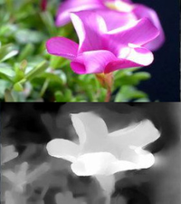
The idea is that a separate auxiliary picture known as the "depth map" is created for each frame or for a series of homogenous frames to indicate depths of objects present in the scene. The depth map is a separate grayscale image having the same dimensions every bit the original 2nd image, with diverse shades of gray to point the depth of every part of the frame. While depth mapping can produce a adequately potent illusion of 3D objects in the video, it inherently does not back up semi-transparent objects or areas, nor does it stand for occluded surfaces; to emphasize this limitation, depth-based 3D representations are oftentimes explicitly referred to every bit two.5D.[vi] [vii] These and other similar issues should be dealt with via a separate method. [6] [eight] [nine]

Generating and reconstructing 3D shapes from single or multi-view depth maps or silhouettes [x]
The major steps of depth-based conversion methods are:
- Depth budget allocation – how much total depth in the scene and where the screen aeroplane will be.
- Image partition, cosmos of mattes or masks, ordinarily by rotoscoping. Each of import surface should exist isolated. The level of detail depends on the required conversion quality and upkeep.
- Depth map cosmos. Each isolated surface should be assigned a depth map. The separate depth maps should be composed into a scene depth map. This is an iterative process requiring adjustment of objects, shapes, depth, and visualization of intermediate results in stereo. Depth micro-relief, 3D shape is added to nearly important surfaces to prevent the "cardboard" effect when stereo imagery looks like a combination of flat images only set at different depths.
- Stereo generation based on 2D+Depth with any supplemental information like clean plates, restored background, transparency maps, etc. When the procedure is complete, a left and right prototype will take been created. Usually the original 2D image is treated as the center prototype, and then that ii stereo views are generated. Nonetheless, some methods propose to use the original image as one eye's image and to generate only the other heart's paradigm to minimize the conversion cost.[4] During stereo generation, pixels of the original paradigm are shifted to the left or to the correct depending on depth map, maximum selected parallax, and screen surface position.
- Reconstruction and painting of any uncovered areas not filled by the stereo generator.
Stereo tin can be presented in any format for preview purposes, including anaglyph.
Time-consuming steps are epitome partition/rotoscoping, depth map cosmos and uncovered area filling. The latter is especially important for the highest quality conversion.
In that location are diverse automation techniques for depth map creation and background reconstruction. For example, automated depth estimation can be used to generate initial depth maps for certain frames and shots.[eleven]
People engaged in such work may exist called depth artists.[12]
Multi-layering [edit]
A evolution on depth mapping, multi-layering works around the limitations of depth mapping by introducing several layers of grayscale depth masks to implement limited semi-transparency. Like to a simple technique,[13] multi-layering involves applying a depth map to more than ane "slice" of the flat paradigm, resulting in a much better approximation of depth and protrusion. The more layers are processed separately per frame, the college the quality of 3D illusion tends to be.
Other approaches [edit]
3D reconstruction and re-projection may be used for stereo conversion. Information technology involves scene 3D model creation, extraction of original prototype surfaces as textures for 3D objects and, finally, rendering the 3D scene from two virtual cameras to acquire stereo video. The approach works well enough in case of scenes with static rigid objects like urban shots with buildings, interior shots, but has bug with non-rigid bodies and soft fuzzy edges.[3]
Another method is to ready both left and correct virtual cameras, both kickoff from the original camera but splitting the offset difference, then painting out apoplexy edges of isolated objects and characters. Essentially clean-plating several groundwork, mid ground and foreground elements.
Binocular disparity can too exist derived from simple geometry.[14]
Automatic conversion [edit]
Depth from motion [edit]
It is possible to automatically gauge depth using different types of movement. In case of camera movement, a depth map of the entire scene can exist calculated. Likewise, object movement can exist detected and moving areas can be assigned with smaller depth values than the background. Occlusions provide information on relative position of moving surfaces.[xv] [16]
Depth from focus [edit]
Approaches of this type are likewise called "depth from defocus" and "depth from mistiness".[fifteen] [17] On "depth from defocus" (DFD) approaches, the depth information is estimated based on the corporeality of blur of the considered object, whereas "depth from focus" (DFF) approaches tend to compare the sharpness of an object over a range of images taken with different focus distances in order to find out its distance to the photographic camera. DFD merely needs two or three at dissimilar focus to properly work, whereas DFF needs x to 15 images at to the lowest degree but is more accurate than the previous method.
If the sky is detected in the processed prototype, it can also be taken into account that more afar objects, besides being hazy, should be more than desaturated and more bluish because of a thick air layer.[17]
Depth from perspective [edit]
The idea of the method is based on the fact that parallel lines, such every bit railroad tracks and roadsides, appear to converge with distance, somewhen reaching a vanishing point at the horizon. Finding this vanishing point gives the farthest point of the whole prototype.[15] [17]
The more the lines converge, the further away they appear to exist. And so, for depth map, the expanse between 2 neighboring vanishing lines can be approximated with a gradient aeroplane.
Conversion artifacts [edit]
- Paper-thin effect is a phenomenon in which 3D objects located at unlike depths appear flat to the audience, as if they were fabricated of cardboard, while the relative depth between the objects is preserved
- Edge sharpness mismatch - this artifact may appear due to a blurred depth map at the boundaries of objects. The border becomes precise in ane view and blurred in another. The edge-sharpness mismatch artifact is typically caused by the following:
- Use of a "safe sheet" technique, defined equally warping the pixels surrounding the occlusion regions to avoid explicit occlusion filling. In such cases, the edges of the deportation map are blurred and the transition betwixt foreground and groundwork regions is smoothed. The region occupied by edge/motion blur is either "stretched" or "tucked," depending on the direction of object displacement. Naturally, this approach leads to mismatches in edge sharpness between the views.
- Lack of proper treatment of semitransparent edges, potentially resulting in edge doubling or ghosting.
- Simple apoplexy-filling techniques leading to stretching artifacts near object edges.
- Stuck to background objects - this error of "sticking" foreground objects to the groundwork
3D quality metrics [edit]
PQM [edit]
PQM[xviii] mimic the HVS equally the results obtained aligns very closely to the Mean Opinion Score (MOS) obtained from subjective tests. The PQM quantifies the distortion in the luminance, and contrast distortion using an approximation (variances) weighted past the mean of each pixel cake to obtain the distortion in an image. This distortion is subtracted from 1 to obtain the objective quality score.
HV3D [edit]
HV3D[19] quality metric has been designed having the human visual 3D perception in heed. It takes into account the quality of the individual right and left views, the quality of the cyclopean view (the fusion of the right and left view, what the viewer perceives), besides every bit the quality of the depth data.
VQMT3D [edit]
The VQMT3D project [20] includes several developed metrics for evaluating the quality of 2D to 3D conversion
| Metric | Class | Blazon | Applicable to |
| Cardboard effect | Advanced | Qualitative | 2D-to-3D conversion |
| Edge-sharpness mismatch | Unique | Qualitative | 2d-to-3D conversion |
| Stuck-to-background objects | Unique | Qualitative | 2d-to-3D conversion |
| Comparison with the second version | Unique | Qualitative | 2D-to-3D conversion |
See as well [edit]
- Autostereoscopy
- Crosstalk (electronics)
- Digital 3D
- Film colorization – many of the problems involved in 3D conversion, such every bit object border identification/recognition, are also encountered in colorization
- Legend3D
- List of 3D films
- Stereoscopic video game – many S-3D video games exercise not actually render two images but employ second + depth rendering conversion techniques too
- Construction from motion
- second-plus-depth
- 3D display
- 3D film
- 3D reconstruction from multiple images
References [edit]
- ^ a b Barry Sandrew. "2d – 3D Conversion Can Be Ameliorate Than Native 3D"
- ^ Irish potato, Mekado (Oct i, 2009). "Fizz and Woody Add a Dimension". The New York Times . Retrieved Feb eighteen, 2010.
- ^ a b Mike Seymour. Art of Stereo conversion: 2D to 3D
- ^ a b c d Scott Squires. second to 3D Conversions
- ^ a b Jon Karafin. Country-of-the-Art 2nd to 3D Conversion and Stereo VFX Archived 2012-04-26 at the Wayback Machine International 3D Society University. Presentation from the October 21, 2011 3DU-Nippon event in Tokyo.
- ^ a b Wu, Jiajun; et al. (2017). MarrNet: 3D Shape Reconstruction via 2.5D Sketches (PDF). Conference on Neural Information Processing Systems (NeurIPS). pp. 540–550.
- ^ Tateno, Keisuke; et al. (2016). When 2.5D is non enough: Simultaneous reconstruction, segmentation and recognition on dense SLAM (PDF). IEEE International Conference on Robotics and Automation (ICRA). pp. 2295–2302.
- ^ Rock, Jason; et al. (2015). Completing 3D Object Shape from One Depth Epitome (PDF). IEEE Conference on Estimator Vision and Blueprint Recognition (CVPR). pp. 2484–2493.
- ^ Shin, Daeyun; et al. (2019). 3D Scene Reconstruction with Multi-layer Depth and Epipolar Transformers (PDF). IEEE International Briefing on Calculator Vision (ICCV). pp. 2172–2182.
- ^ "Soltani, A. A., Huang, H., Wu, J., Kulkarni, T. D., & Tenenbaum, J. B. Synthesizing 3D Shapes via Modeling Multi-View Depth Maps and Silhouettes With Deep Generative Networks. In Proceedings of the IEEE Briefing on Estimator Vision and Pattern Recognition (pp. 1511-1519)". GitHub. 2019-07-eleven.
- ^ YUVsoft. 2nd–to–Stereo 3D Conversion Process
- ^ Mike Eisenberg (31 Oct 2011). "Interview with 3D Artist Adam Hlavac". Screen Rant . Retrieved 28 December 2015.
- ^ Cutler, James. "Masking Multiple Layers in Adobe Photoshop". Archived from the original on January eighteen, 2012.
- ^ Converting a 2d picture to a 3D Lenticular Print
- ^ a b c Dr. Lai-Man Po. Automatic 2d-to-3D Video Conversion Techniques for 3DTV Department of Electronic Applied science, City Academy of Hong Kong. 13 April 2010
- ^ Automatic 2D to 2D-plus-Depth conversion sample for a camera motion scene
- ^ a b c Qingqing We. "Converting 2D to 3D: A Survey" (PDF). Faculty of Electrical Applied science, Mathematics and Reckoner Science, Delft University of Engineering science. Archived from the original (PDF) on 2012-04-15.
- ^ Joveluro, P.; Malekmohamadi, H.; Fernando, W. A. C; Kondoz, A. M. (2010). Perceptual Video Quality Metric for 3D video quality cess. IEEE. doi:x.1109/3dtv.2010.5506331.
- ^ Banitalebi-Dehkordi, Amin; Pourazad, Mahsa T.; Nasiopoulos, Panos (2013). 3D video quality metric for 3D video pinch. IEEE. arXiv:1803.04629. doi:ten.1109/ivmspw.2013.6611930.
- ^ VQMT3D
- Mansi Sharma; Santanu Chaudhury; Brejesh Lall (2014). Kinect-Variety Fusion: A Novel Hybrid Arroyo for Artifacts-Free 3DTV Content Generation. In 22nd International Conference on Pattern Recognition (ICPR), Stockholm, 2014. doi:10.1109/ICPR.2014.395.
justiceartudistrums.blogspot.com
Source: https://en.wikipedia.org/wiki/2D_to_3D_conversion
0 Response to "2d to 3d drawing conversion jobs"
Post a Comment